Elevator Stilts

Project Objective
As part of the capstone mechanical engineering design project, our team was tasked with designing and manufacturing a pair of performance stilts for the National Stiltwalkers of Canada. The primary objective was to create stilts that could be adjusted in height during a live performance, something not available in the current market.
The client outlined key requirements for the design:
-
The stilts must extend by at least 18 inches.
-
Each stilt should weigh no more than 4 kg.
-
Manufacturing costs should be kept as low as possible while maintaining performance and safety standards.
-
The height-adjustment mechanism should be intuitive and user-friendly, allowing performers to change the setting seamlessly during shows.
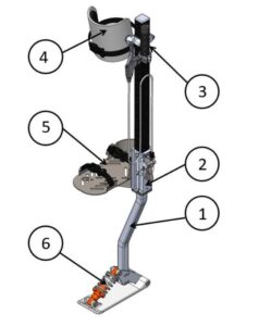
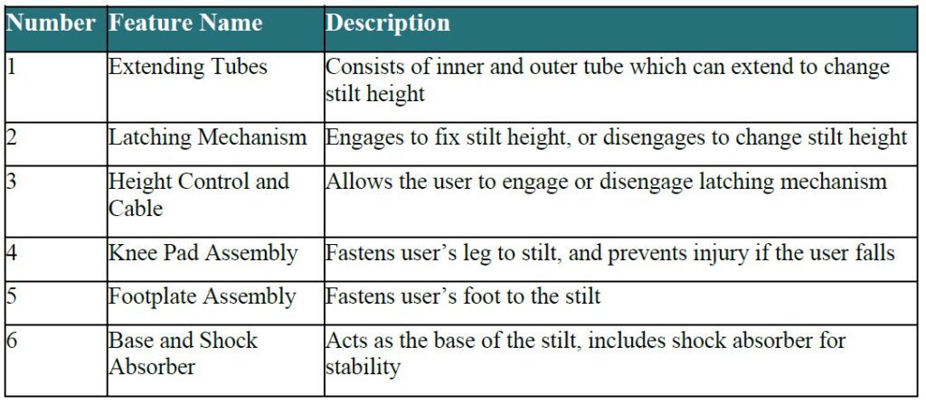
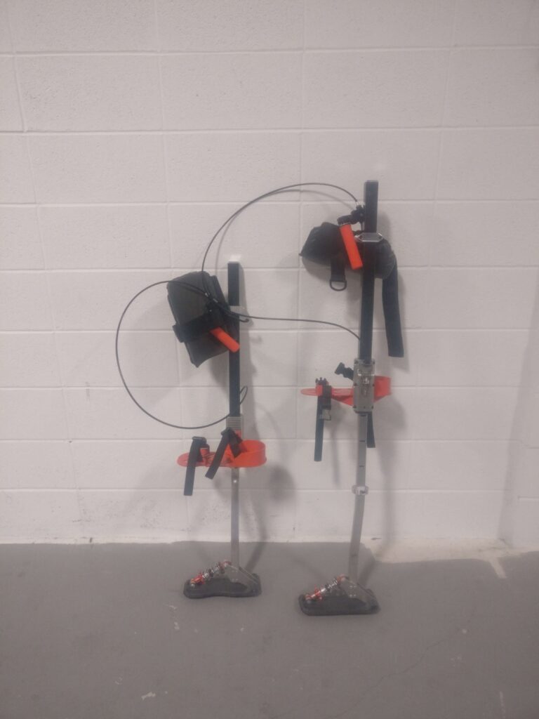
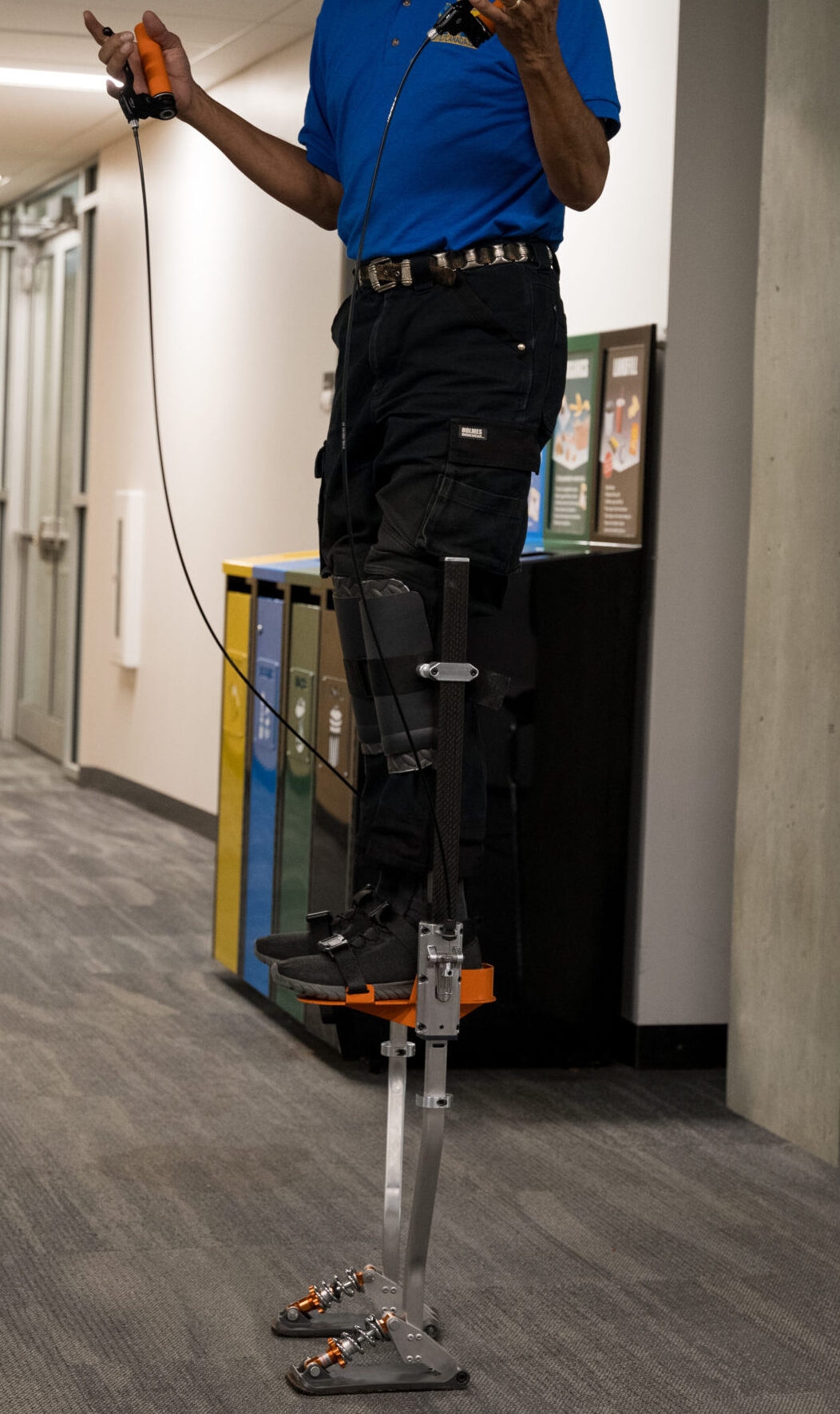
The final design is a mechanical stilt system with six main assemblies: inner and outer tubes, brake lever with cable, toggle pin lock, footplate, kneepad assembly, and a shock-absorbing base. A brake lever allows performers to quickly lock or adjust the stilt height.
Assembly 1 - Extending Tubes
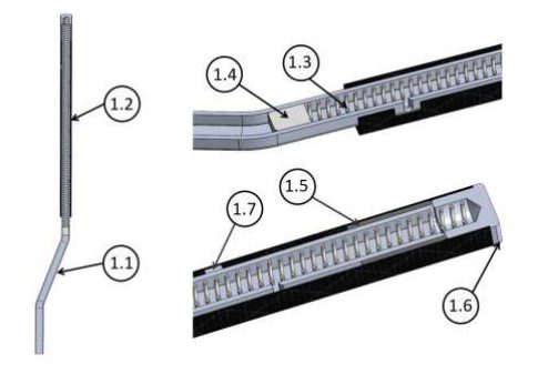
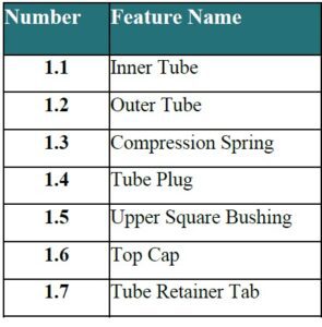
The stilt body features two sliding tubes: a lightweight aluminum lower tube connected to the base and a carbon fiber upper tube connected to the footplate. A compression spring inside enables smooth extension when the latch is disengaged, while precision bushings and retainers ensure stability and prevent over-travel. Height adjustment is secured through slots machined at 3-inch intervals for the toggle mechanism.
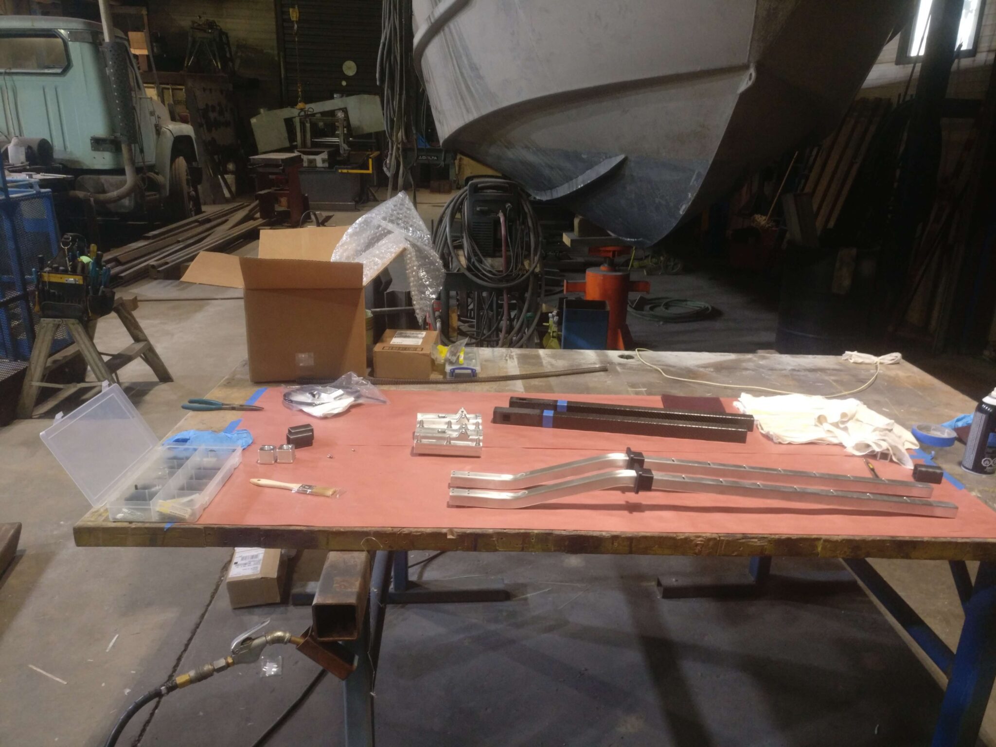
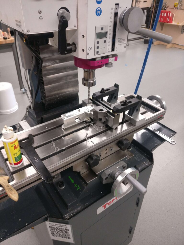
Key fabrication methods included CNC milling for slots and fittings, tube bending for alignment of the base, and precision cutting of carbon fiber components.
Assembly 2 - Latching Mechanism
The latching mechanism locks the inner and outer tubes in place and releases them for smooth height adjustment. A toggle with torsional spring engages automatically to prevent motion, and is disengaged via a cable brake control, allowing performers to change height seamlessly.
Key components were manufactured using CNC machining (side housings, toggle, bushing), fiber laser cutting (steel bracket), and lathe operations (toggle pin). The toggle spring was hand-formed, while standard stock parts were used for fasteners and fittings.
Assembly 3 - Height Controls
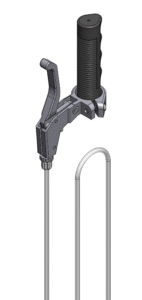
Height adjustment is controlled by a brake lever and cable system. Pulling the lever disengages the toggle, allowing the inner and outer tubes to slide. Releasing the lever re-engages the toggle into the nearest slot, securely fixing the stilt height.
The assembly uses stock components for the brake lever, handle, cable, and gland, ensuring reliability and ease of replacement.
Assembly 4 - Kneepad
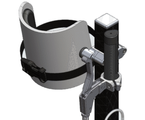
The kneepad assembly secures the user’s leg to the stilt, providing stability and reducing injury risk in case of a fall. It consists of a padded kneepad with a strap-and-buckle system, mounted to the top of the carbon fiber tube with CNC-machined aluminum support clamps.
The prototype used stock components (kneepad, foam, straps, fasteners, O-ring, buckle) adapted from an existing fixed-length stilt for efficiency and reliability.
Assembly 5 - Footplate
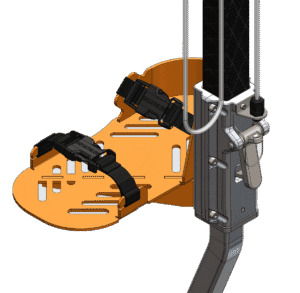
The footplate assembly secures the user’s foot to the stilt with dual strap-and-buckle fasteners. It is mounted to the latching mechanism with screws, moving in sync with the outer carbon fiber tube for smooth height adjustment.
Fabrication included fiber laser cutting of the foot holder, backer, and support from sheet steel, while screws, straps, and buckles were sourced as stock parts for reliability.

Assembly 6 - Base and Shock Absorber
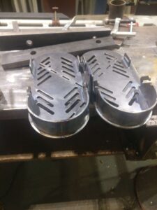
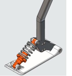
The base assembly consists of a baseplate, shock absorber, and ankle plates, mounted to the bottom of the inner tube. Its wide foot pad and integrated shock absorber provide stability, allowing the user to balance and remain stationary—an improvement over traditional peg stilts.
Fabrication included CNC machining of the PVC foot pad and fiber laser cutting of sheet metal ankle plates. The shock absorber and fasteners were stock components.
Analysis
Toggle Stress Analysis
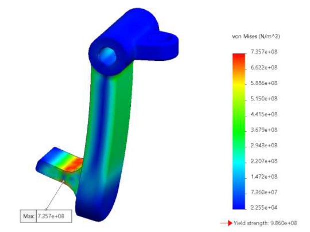
Finite Element Analysis (FEA) confirmed the toggle mechanism could safely support a 300 lb (136 kg) user, with a safety factor of 3.85 under normal conditions. Even under extreme impact (simulating a 300 lb user jumping 15″), the toggle maintained a safety factor of 1.34. While not optimized for jumping, the design met client requirements for safe mid-performance height adjustment.
Fatigue Life
Goodman fatigue analysis indicated the aluminum tube will withstand 500 million cycles (≈83,000 hours of use) with a safety factor of 19.5, ensuring long-term durability well beyond performance demands.
Final Results and Skills Developed
The project concluded with the successful design and fabrication of a fully functional prototype that met the client’s key requirements for adjustable height, weight, cost, and usability. The final design demonstrated reliable performance during testing, validating both the engineering analysis and user-focused design decisions.
Skills Developed:
-
CAD modeling & simulation (SolidWorks)
-
Precision fabrication techniques (CNC machining, fiber laser cutting, composite cutting, hand-forming)
-
Mechanical systems design (latching mechanisms)
-
Prototyping under constraints (balancing weight, cost, and performance requirements)

